4 Things to Know When Choosing a Current Sensor Circuit Diagram Flux Gate Sensor Current Sensing Method. A saturable Inductor is the main component for the Fluxgate sensing technique. Due to this, Fluxgate sensor is called as Saturable Inductor Current Sensor. The inductor core which is used for the fluxgate sensor works in the saturation region. Ways to measure current: 1- Indirect method: such as current transformers (in the figure) and Hall effect sensors, which relies on Faraday's law of induction to sense current in a circuit and convert it to a proportional voltage. These methods are suitable more for high current systems. 2- Direct method: which relies on Ohm's law which states that V = I x R.

The hall effect sensor is more costly and complex to implement. An advantage to using the hall effect sensor method is its ability to work with higher current and it provides electrical isolation if a particular device has multiple sources of power. In this article, we will focus on building a current sensor circuit using a current sense resistor. Introduction to Current Sense Amplifiers 4 Integrating the Current Sensing Signal Path 6 Integrated, Current Sensing Analog-to-Digital Converter 8 Integrating the Current Sensing Resistor 11 Common uses for Multi-Channel Current Monitoring 13 2. Out-of-range current measurements with current-sense amplifiers Measuring Current to Detect Out-of-Range
How to measure current using Arduino and ACS712 current sensor Circuit Diagram
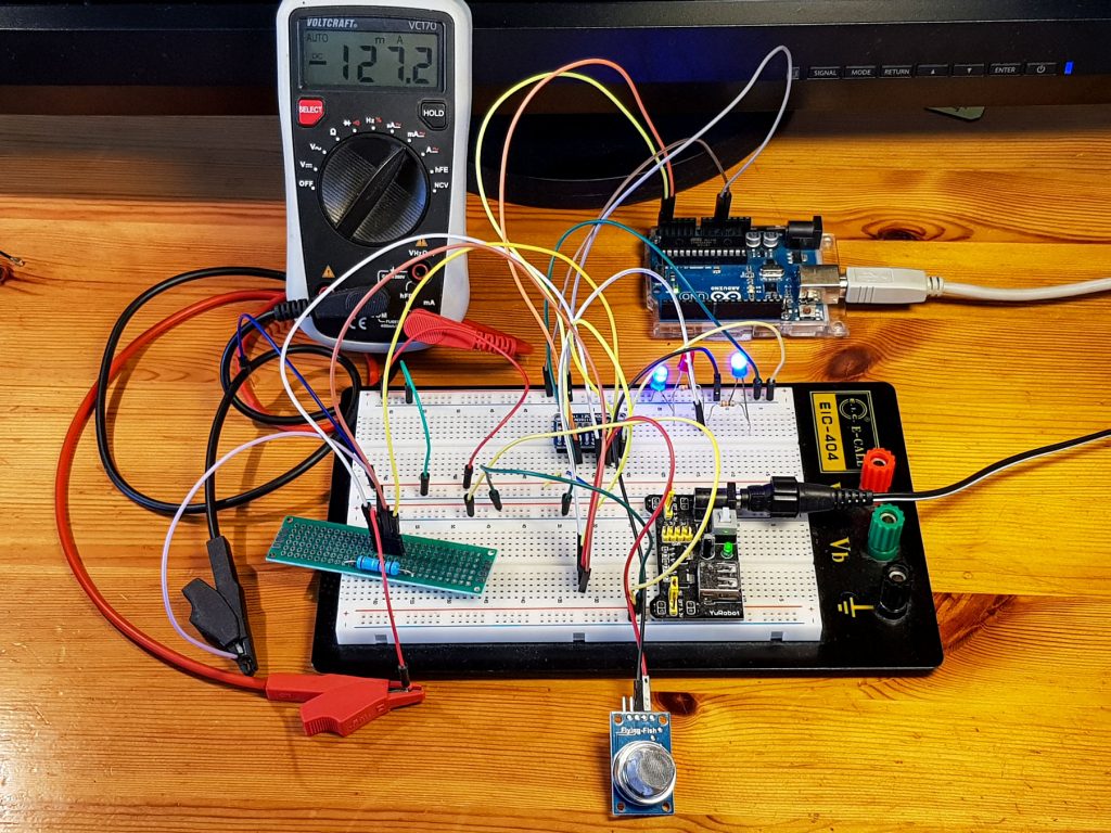
The current sensor switch circuit diagram is shown below. Generally, current sensors are mainly used where there is a necessity for the measurement of the amount of current used by a particular device or appliance. There are different techniques are available to measure the flow of current. So in this circuit, we are using a Hall effect current The typical current of such a circuit would be at around 0.020A. Since the smallest current range of the ACS712 is 5 Ampere, you will not get much of a signal on the sensor output. In this tutorial, we explored how to use the ACS712 current sensor with an Arduino to measure both DC and AC currents. By understanding the working principle of

Acs712 current sensor can measure both direct and alternating current. For this post/tutorial/project I am going to measure only dc current. Formula which i derived and explained in the tutorial is only for direct current measurement. You can not use the below formula to measure alternating current with acs712 hall effect current sensor. current to an easily measured output voltage, which is proportional to the current through the measured path. There are a wide variety of sensors, and each sensor is suitable for a specific current range and environmental condition. No one sensor is optimum for all applications. Among these sensors, a current sensing resistor is the most
Hall Effect current sensor circuit with Arduino Circuit Diagram
The typical application circuit using the ASC712 Current Sensor is given in its datasheet and the following images shows the same. ACS712 Current Sensor Module. Using one of the variants of the ACS712 IC (5A, 20A or 30A), several manufacturers developed ASC712 Current Sensor Module boards that can be easily interfaced to a microcontroller like