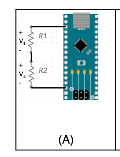
Circuits Equation and Applications Circuit Diagram The most basic and commonly used voltage divider circuit is that of two fixed-value series resistors, but a potentiometer or rheostat can also be used for voltage division by simply adjusting its wiper position. A very common application of a voltage divider circuit is to replace one of the fixed-value resistors with a sensor. In this video, I am talking about what is a voltage divider, how it works, and how to use it as a voltage sensor.Join this channel to support me or to get ac

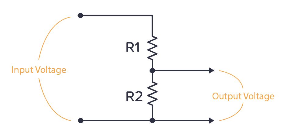
Figure 2: Resistive Voltage Divider Circuit. The input voltage V in is applied across the two resistors R 1 & R 2 which are connected in series. The output voltage V out is obtained between the two terminals of the resistor R 2. The voltage across this resistor will be a fraction of the input voltage V in. The formula to calculate the output of Ideal Voltage Divider There are two important parts to the voltage divider: the circuit and the equation. The Circuit A voltage divider involves applying a voltage source across a series of two resistors. You may see it drawn a few different ways, but they should always essentially be the same circuit. Examples of voltage divider schematics. This is where the hero: A voltage divider comes in and saves the day acting as a level shifter which interfaces two circuits that use different operating voltages. The voltage divider can help level the voltage down from a microcontroller (eg. 5V to 3.3V) to avoid damage to the sensor which makes it safe for the sensor to handle.
Circuits, Equation and Applications Circuit Diagram
A voltage divider is a circuit that creates a smaller voltage from an input voltage by using two resistors. You'll see it in both simple and advanced circuits all the time. Here's the basic setup: For example, the thermistor is a temperature sensor. It changes its resistance based on the temperature. Key learnings: Voltage Divider Definition: A voltage divider is a simple circuit that creates a part of its input voltage as output, using two resistors in series.; Circuit Components: The circuit includes two resistors connected in series with a voltage source, splitting the input voltage.; Unloaded Equation: With no current flowing out, the output voltage depends on the ratio of the resistors. A voltage divider is a simple yet powerful circuit that reduces a higher voltage to a lower one using two resistors. It is commonly used to reduce the voltage for devices that require lower operating voltages, such as sensors or microcontrollers. The output voltage of a voltage divider can be calculated using the voltage divider equation: Where:

A voltage divider is a simple circuit which turns a large voltage into a smaller one. Using just two series resistors and an input voltage, we can create an output voltage that is a fraction of the input. Real-life voltage divider applications. Suggested Reading. This tutorial builds on basic electronics knowledge. If you haven't already