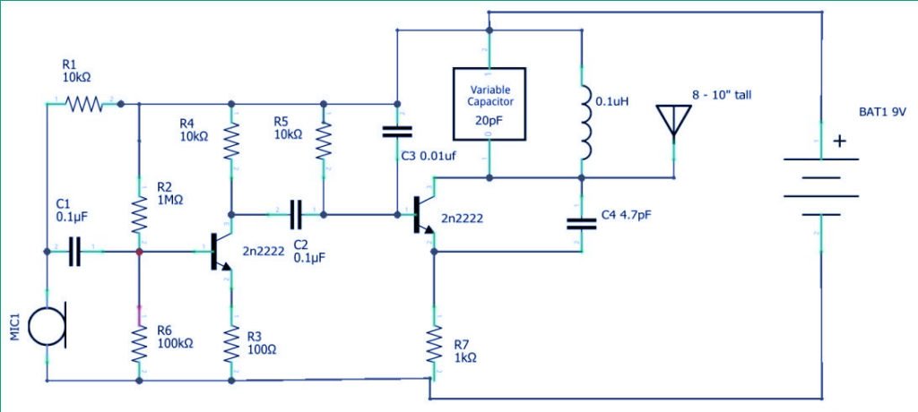
How to build FM transmitter circuit Circuit Diagram FM Transmitter Circuit Diagram and Explanation. Connect the components as shown in the Simple FM transmitter circuit below. This is how this simple FM transmitter circuit looks on breadboard . The audio output signal from the microphone is usually small, the first transistor thus performs the job of amplifying that signal to a level good enough
Our detailed guides, tutorials, and circuit diagrams provide step-by-step instructions, optimization tips, and creative ideas for building and customizing FM transmitter circuits. Share your audio content with the world using our curated selection of high-quality FM transmitter circuit. SMD FM Transmitter. Let's construct a low-power FM transmitter using surface-mount devices (SMD) that will be received with a standard FM radio. Soldering surface mounted devices is not so hard and actually is quite easy. The figure below shows the schematic of the transmitter which consists of two stages: an oscillator and an output amplifier.

FM Transmitter Circuits Circuit Diagram
This is a simple wireless FM transmitter circuit which uses RF communication to transmit the medium or low power FM signal. Its maximum range is 2 km. Skip to content Circuit Diagram of 2 km FM Transmitter Circuit: FM Transmitter Circuit Diagram - ElectronicsHub.Org Circuit Components: Component Name Value; R1: 18K: R2: 22K: R3: 90K: R4 Learn how to make a simple FM transmitter circuit with a transistor, inductor, capacitor, and antenna. See the block diagram, working, application, and advantages of this circuit.
In this post, we'll break down the basics of FM transmitter circuit diagrams and how they can be used to listen to your favorite music on-the-go. An FM transmitter is an electronic device which converts signals from audio devices such as cell phones, computers or MP3 players and transmits them into FM frequencies that can be picked up by car

FM Transmitter Circuit Working and Its Applications Circuit Diagram
FM Transmitter Circuit. Working Explanation. The major game here is the Antenna and the Mic. The Mic converts sound waves into an electrical voltage which is filtered via a resistor-capacitor network and amplified using the 2N3904 Transistor. The amplified signal is then transmitted for propagation via the antenna. A list of FM transmitter circuits with schematic diagrams for hobby and project purposes.Includes short and long range, simple and easy transmitters. Home; DIY Electronic Projects Stereo FM Transmitter using BA1404 IC - This is a stereo FM transmitter circuit using an IC from Rohmm semiconductors named BA1404 - which is a monolithic IC
